Spool Orifice Hydraulic Force
(To be removed) Axial hydraulic force exerted on spool
The Hydraulics (Isothermal) library will be removed in a future release. Use the Isothermal Liquid library instead. (since R2020a)
For more information on updating your models, see Upgrading Hydraulic Models to Use Isothermal Liquid Blocks.
Library
Valve Forces

Description
The Spool Orifice Hydraulic Force block simulates the steady-state axial hydraulic force exerted on the spool by fluid flowing through the orifice. The spool is assumed to be sharp-edged. You have two parameterization options:
A rectangular slot, to be used with the Orifice with Variable Area Slot block
A round hole, or a set of round holes, to be used with the Orifice with Variable Area Round Holes block
The width of the slot, or the diameter of the holes, must be considerably larger than the radial clearance between the spool and the sleeve. Connect the Spool Orifice Hydraulic Force block in series with the respective orifice block to monitor the flow rate.
The force is simulated according to the following equations:
For rectangular slot,
For round holes,
where
| F | Axial hydraulic force |
| q | Flow rate through the orifice |
| ρ | Fluid density |
| A | Orifice area |
| Θ | Jet angle (rad) |
| x0 | Orifice initial opening |
| s | Spool displacement |
| b | Orifice width, for rectangular slot |
| D | Orifice diameter, for round holes |
| Z | Number of round holes |
| δ | Radial clearance |
| or | Orientation parameter with respect to the globally assigned positive direction. If the orifice is opened while the spool is shifted in positive direction, or equals 1. If the orifice is opened while the spool is shifted in negative direction, or equals –1. |
Connections A and B are hydraulic conserving ports that should be connected in series with the orifice block to monitor the flow rate. Connection S is a physical signal port that provides the spool displacement. Connection F is a physical signal port that outputs the hydraulic axial force value. This port should be connected to the control port of an Ideal Force Source block. The force computed in the block always acts to close the orifice.
Basic Assumptions and Limitations
The transient effects are assumed to be negligible.
The jet angle approximation is based on the Richard von Mises equation.
The jet angle variation with the orifice opening is identical for the rectangular slot and the round holes orifices.
The block can be used with orifices whose width or diameter is considerably larger than the axial opening.
Parameters
- Orifice type
Select the type of orifice:
Rectangular slot— Orifice created by the sharp-edged spool and a rectangular slot in the sleeve. This is the default.Round holes— Orifice created by the sharp-edged spool and a set of round holes evenly distributed along the sleeve perimeter.
- Orifice width
Orifice width. The parameter must be greater than zero. The default value is
0.01m. The parameter is used if Orifice type is set toRectangular slot.- Diameter of round holes
Orifice diameter. If multiple orifices are used, all of them must be of the same diameter, identically aligned with respect to the spool edge, and spaced evenly among the sleeve perimeter. The parameter must be greater than zero. The default value is
0.005m. The parameter is used if Orifice type is set toRound holes.- Number of round holes
Number of round holes in the sleeve. The parameter must be greater than zero. The default value is
4. The parameter is used if Orifice type is set toRound holes.- Radial clearance
The radial clearance between the spool and the sleeve. The default value is
1e-5m.- Initial opening
Orifice initial opening. The parameter can be positive (underlapped orifice), negative (overlapped orifice), or equal to zero for zero lap configuration. The default value is
0.- Orifice orientation
The parameter is introduced to specify the effect of the force on the orifice opening. The parameter can be set to one of two options:
Opens in positive directionorOpens in negative direction. The valueOpens in positive directionspecifies an orifice that opens when the spool moves in the globally assigned positive direction. The default value isOpens in positive direction.
Ports
The block has the following ports:
AHydraulic conserving port associated with an orifice inlet.
BHydraulic conserving port associated with an orifice outlet.
SPhysical signal port that provides the spool displacement.
FPhysical signal port that outputs hydraulic axial force.
Examples
The following example shows a model of a 4-way, 3-position, hydraulically-operated directional valve where the hydraulic axial forces acting on the spool are being taken into consideration.
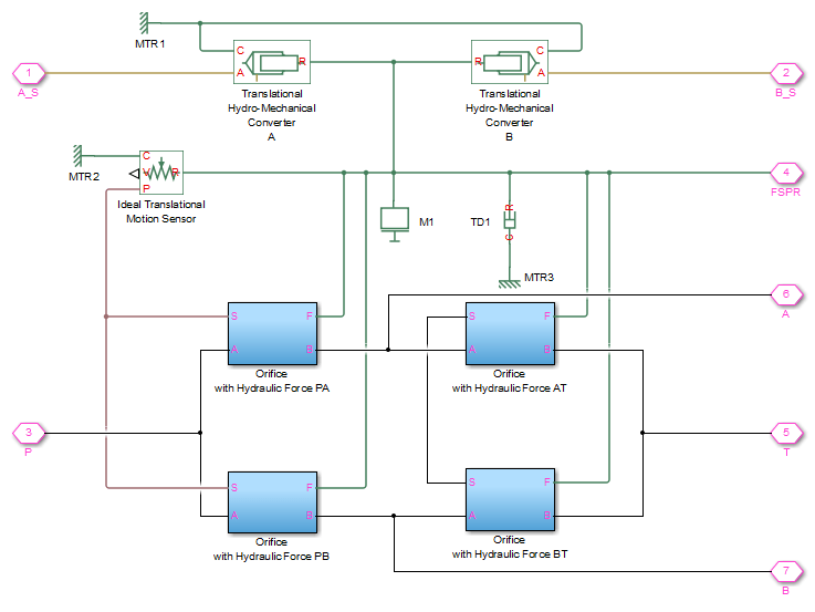
The spool (mass M1, viscous friction TD1) is
shifted by the servo-actuator simulated by two Translational Hydro-Mechanical
Converter blocks. Connections A_S and B_S are hydraulic ports for applying
pilot control pressure.
Four variable orifices are represented by subsystems:
Orifice with Hydraulic Force PA
Orifice with Hydraulic Force PB
Orifice with Hydraulic Force AT
Orifice with Hydraulic Force BT
The structure of a subsystem is shown in the following illustration.
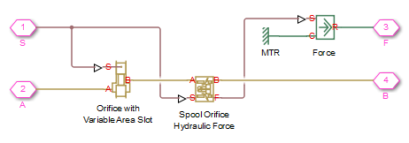
It consists of an Orifice with Variable Area Slot block, which simulates hydraulic properties of the orifice, connected in series with a Spool Orifice Hydraulic Force block. The force value computed in the block is exported through its port F and passed to the Force block.
The forces on all four orifices (F_PA, F_PB,
F_AT, F_BT) are applied to the valve spool as
it is shown in the first schematic.
For more details and for parameter settings, see the Servo-Valve Controlling Hydraulic Actuator example.
Extended Capabilities
Version History
Introduced in R2007aSee Also
You can also select a web site from the following list:
Americas
- América Latina (Español)
- Canada (English)
- United States (English)
Europe
- Belgium (English)
- Denmark (English)
- Deutschland (Deutsch)
- España (Español)
- Finland (English)
- France (Français)
- Ireland (English)
- Italia (Italiano)
- Luxembourg (English)
- Netherlands (English)
- Norway (English)
- Österreich (Deutsch)
- Portugal (English)
- Sweden (English)
- Switzerland
- United Kingdom (English)