Pulse Generator (Thyristor)
Generate pulses for twelve-pulse and six-pulse thyristor converters
Libraries:
Simscape /
Electrical /
Specialized Power Systems /
Power Electronics /
Power Electronics Control
Description
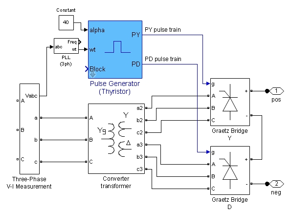
The Pulse Generator (Thyristor) block generates two pulse trains. These control a twelve-pulse thyristor converter made of two three-phase full-wave thyristor bridges (also called Graetz bridges). In steady-state condition, each pulse train consists of six equidistant square pulses with 60 degrees shift between them.
The first set of pulses (PY) is sent to the six-pulse bridge connected to the wye (Y) secondary winding of the Y/Y/Delta converter transformer. The second set of pulses (PD) is sent to the six-pulse bridge connected to the delta secondary winding of the converter transformer. The PD pulses can be set to lead or lag the PY pulses by 30 electrical degrees, depending on the configuration of the delta connection of the converter transformer.
The following figure shows an example of a Pulse Generator (Thyristor) block connected to a twelve-pulse thyristor converter.
The Pulse Generator (Thyristor) block can be programmed to control a six-pulse thyristor converter made of one three-phase full-wave thyristor bridge. In this configuration, the PD pulse train is not generated and the block outputs only the PY pulse train. The pulse train, renamed P, is suitable for a Graetz bridge connected to a converter transformer, with no phase shift between primary and secondary windings.
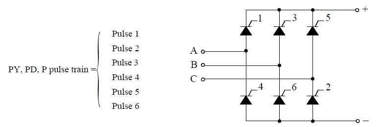
The pulse ordering in the pulse trains corresponds to the natural order of commutation of a three-phase thyristor bridge, as shown in the following figure.
The table below gives the commutating voltages for the thyristors according to the transformer connection. The transformer connection reflects the phase shift between the AC source and the thyristors.
| Thyristor to be ignited | 1 | 2 | 3 | 4 | 5 | 6 |
| Thyristor to be extinguished | 5 | 6 | 1 | 2 | 3 | 4 |
| Commutating voltage for a Y-Y connection | Vac | Vbc | Vba | Vca | Vcb | Vab |
| for a Y-D1 (lagging) | -Vc | Vb | -Va | Vc | -Vb | Va |
| for a Y-D11 (leading) | Va | -Vc | Vb | -Va | Vc | -Vb |
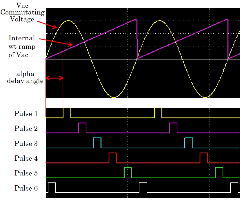
The Pulse Generator (Thyristor) block is controlled by the alpha angle reference
signal and by the synchronization signal wt. The wt signal is an
angle varying between 0 and 2*pi radians, synchronized on zero crossings of the
fundamental (positive-sequence) of phase A of the primary voltage of the converter
transformer. The wt signal is normally obtained from a phase locked loop (PLL)
system.
The Pulse Generator (Thyristor) block generates internal wt ramps to control the pulses. The alpha delay angle is expressed in electrical degrees by which the pulse is delayed relative to angle zero of its commutating voltage. The figure shows how the PY pulse train is generated.
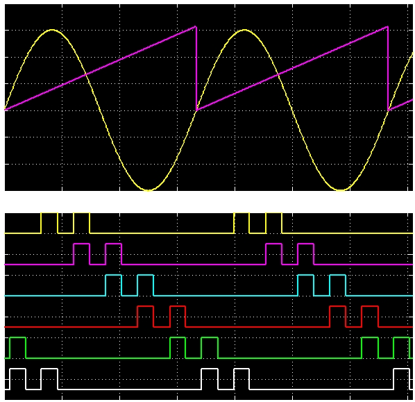
The Pulse Generator (Thyristor) block can be configured to work in double-pulsing mode. In this mode two pulses are sent to each thyristor: a first pulse when the alpha angle is reached, and then a second pulse 60 degrees later, when the next thyristor is fired. This figure shows the double pulses in a PY pulse train.
Characteristics
| Sample Time | Specified in the Sample Time parameter |
| Scalar Expansion | No |
| Dimensionalized | No |
| Zero-Crossing Detection | Yes |
Examples
The power_PulseGenerator example shows various uses of the
pulse generator.
The model sample time is parameterized with the variable Ts (default value Ts = 50e-6). To simulate continuous mode, specify Ts = 0 in the MATLAB® Command Window.
Ports
Input
Output
Parameters
Extended Capabilities
Version History
Introduced in R2013a
See Also
You can also select a web site from the following list:
Americas
- América Latina (Español)
- Canada (English)
- United States (English)
Europe
- Belgium (English)
- Denmark (English)
- Deutschland (Deutsch)
- España (Español)
- Finland (English)
- France (Français)
- Ireland (English)
- Italia (Italiano)
- Luxembourg (English)
- Netherlands (English)
- Norway (English)
- Österreich (Deutsch)
- Portugal (English)
- Sweden (English)
- Switzerland
- United Kingdom (English)