SVPWM Generator (2-Level)
Generate pulses for SVPWM-controlled two-level converter
Libraries:
Simscape /
Electrical /
Specialized Power Systems /
Power Electronics /
Power Electronics Control
Description
The SVPWM Generator (2-Level) block generates pulses for three-phase two-level DC/AC converters using the space-vector pulse width modulation (SVPWM) technique.
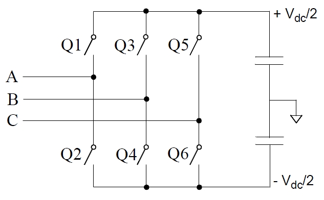
The converter switches are represented by the following equivalent circuit:
As shown in the following figure, the objective of the SVPWM technique is to approximate the reference voltage vector (Uref) instantaneously by combining the switching states corresponding to the basic space vectors.
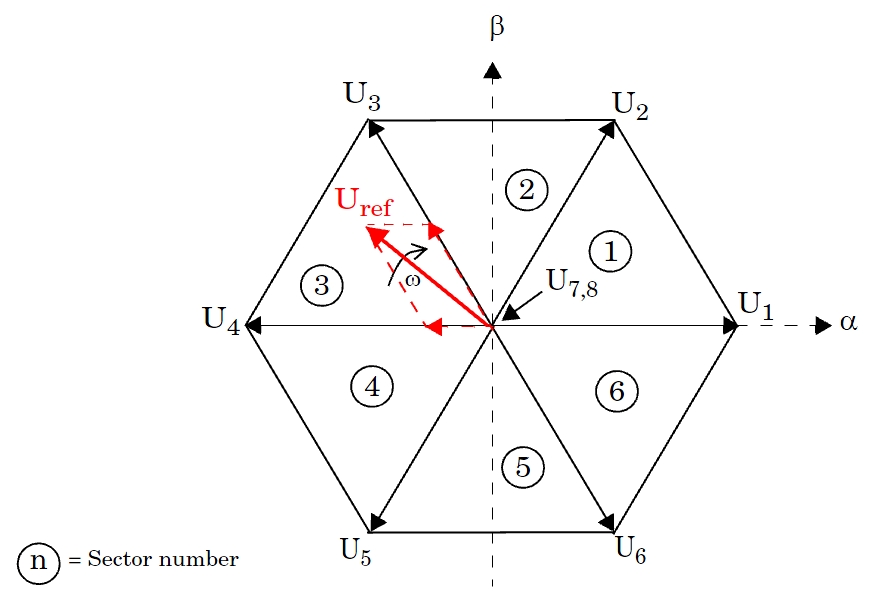
More precisely, for every PWM period, the reference vector Uref is averaged by using its two adjacent space vectors (U3 and U4 in the figure) for a certain duration of time and a null vector (U7 or U8) for the rest of the period.
| Vector | Q1 | Q3 | Q5 |
|---|---|---|---|
| U1 | 1 | 0 | 0 |
| U2 | 1 | 1 | 0 |
| U3 | 0 | 1 | 0 |
| U4 | 0 | 1 | 1 |
| U5 | 0 | 0 | 1 |
| U6 | 1 | 0 | 1 |
| U7 | 0 | 0 | 0 |
| U8 | 1 | 1 | 1 |
The block implements two symmetrical switching patterns[1]:
Pattern #1: With this pattern, known as Software-Determined, each PWM channel switches twice per every PWM period.
Pattern #2: With this pattern, known as Hardware-Determined, one PWM channel remains constant for the entire PWM period. Consequently, the number of switching times for this pattern is less than pattern #1. As a result, switching losses are reduced with Pattern #2.
Characteristics
| Sample Time | Specified in the Sample Time
parameter Continuous if Sample Time = 0 |
| Scalar Expansion | No |
| Dimensionalized | No |
Examples
The power_SVPWMGenerator2Level model uses two simple
circuits to show how the SVPWM Generator (2-Level) works and to compare the two
switching pattern options. Run the simulation and open the FFT Analysis tool of the
Powergui block to see the harmonics and the THD value of the voltages produced by
the two converters.
The model sample time is parameterized by the Ts variable set to a default value
of 2e-6 s. Set Ts to 0 in the command window and change the Simulation
type parameter of the Powergui block to
Continuous to simulate the model in continuous
mode.
Ports
Input
Output
Parameters
References
[1] Yu, Z., Application Report SPRA524, Space-Vector PWM with TMS320C24x Using H/W & S/W Determined Switching Patterns, Texas Instruments, 1999.
Extended Capabilities
Version History
Introduced in R2013a
See Also
You can also select a web site from the following list:
Americas
- América Latina (Español)
- Canada (English)
- United States (English)
Europe
- Belgium (English)
- Denmark (English)
- Deutschland (Deutsch)
- España (Español)
- Finland (English)
- France (Français)
- Ireland (English)
- Italia (Italiano)
- Luxembourg (English)
- Netherlands (English)
- Norway (English)
- Österreich (Deutsch)
- Portugal (English)
- Sweden (English)
- Switzerland
- United Kingdom (English)