Main Content

Second-Order Integrator

Second-order integration of input signal

  • Second-Order Integrator block

Libraries:
Simulink / Continuous

Description

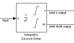
The Second-Order Integrator block and the Second-Order Integrator Limited block solve the second-order initial value problem:

d2xdt2=u,dxdt|t=0=dxo,x|t=0=xo,

where u is the input to the system. The block is therefore a dynamic system with two continuous states: x and dx/dt.

Note

These two states have a mathematical relationship, namely, that dx/dt is the derivative of x. To satisfy this relationship throughout the simulation, Simulink places various constraints on the block parameters and behavior.

The Second-Order Integrator Limited block is identical to the Second-Order Integrator block with the exception that it defaults to limiting the states based on the specified upper and lower limits. For more information, see Limiting the States.

Simulink® software can use several different numerical integration methods to compute the outputs of the block. Each has advantages for specific applications. Use the Solver pane of the Configuration Parameters dialog box to select the technique best suited to your application. (For more information, see Solver Selection Criteria.) The selected solver computes the states of the Second-Order Integrator block at the current time step using the current input value.

Use the block parameter dialog box to:

  • Specify whether the source of each state initial condition is internal or external

  • Specify a value for the state initial conditions

  • Define upper and lower limits on either or both states

  • Specify absolute tolerances for each state

  • Specify names for both states

  • Choose an external reset condition

  • Enable zero-crossing detection

  • Reinitialize dx/dt when x reaches saturation

  • Specify that Simulink disregard the state limits and external reset for linearization operations

Defining Initial Conditions

You can define the initial conditions of each state individually as a parameter on the block dialog box or input one or both of them from an external signal.

  • To define the initial conditions of state x as a block parameter, use the Initial condition source x drop-down menu to select internal and enter the value in the Initial condition x field.

  • To provide the initial conditions from an external source for state x, specify the Initial condition source x parameter as external. An additional input port appears on the block.

  • To define the initial conditions of state dx/dt as a block parameter, use the Initial condition source dx/dt drop-down menu to select internal and enter the value in the Initial condition dx/dt field.

  • To provide the initial conditions from an external source for state dx/dt, specify Initial condition source dx/dt as external. An additional input port appears on the block.

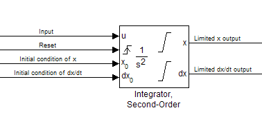
If you choose to use an external source for both state initial conditions, your block appears as follows.

Note

  • Simulink does not allow initial condition values of inf or NaN.

  • If you limit state x or state dx/dt by specifying saturation limits (see Limiting the States) and one or more initial conditions are outside the corresponding limits, then the respective states are initialized to the closest valid value and a set of consistent initial conditions is calculated.

Limiting the States

When modeling a second-order system, you may need to limit the block states. For example, the motion of a piston within a cylinder is governed by Newton's Second Law and has constraints on the piston position (x). With the Second-Order Integrator block, you can limit the states x and dx/dt independent of each other. You can even change the limits during simulation; however, you cannot change whether or not the states are limited. An important rule to follow is that an upper limit must be strictly greater than its corresponding lower limit.

The block appearance changes when you limit one or both states. With both states limited, the block appears as follows.

For each state, you can use the block parameter dialog box to set appropriate saturation limits.

Limiting x Only

If you use the Second-Order Integrator Limited block, both states are limited by default. But you can also manually limit state x on the Second-Order Integrator block by selecting Limit x and entering the limits in the appropriate parameter fields.

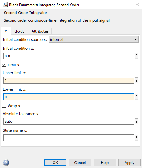
The block then determines the values of the states as follows:

  • When x is less than or equal to its lower limit, the value of x is held at its lower limit and dx/dt is set to zero.

  • When x is in between its lower and upper limits, both states follow the trajectory given by the second-order ODE.

  • When x is greater than or equal to its upper limit, the value of x is held at its upper limit and dx/dt is set to zero.

You can choose to reinitialize dx/dt to a new value at the time when x reaches saturation. See Reinitializing dx/dt When x Reaches Saturation.

Limiting dx/dt Only

As with state x, state dx/dt is set as limited by default on the dx/dt pane of the Second-Order Integrator Limited block dialog box. You can manually set this parameter, Limit dx/dt, on the Second-Order Integrator block. In either case, you must enter the appropriate limits for dx/dt.

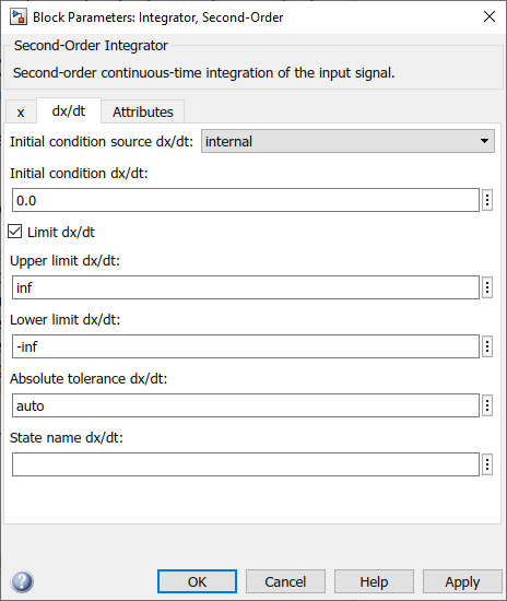
If you limit only the state dx/dt, then the block determines the values of dx/dt as follows:

  • When dx/dt is less than or equal to its lower limit, the value of dx/dt is held at its lower limit.

  • When dx/dt is in between its lower and upper limits, both states follow the trajectory given by the second-order ODE.

  • When dx/dt is greater than or equal to its upper limit, the value of dx/dt is held at its upper limit.

When state dx/dt is held at it upper or lower limit, the value of x is governed by the first-order initial value problem:

dxdt=L,x(tL)=xL,

where L is the dx/dt limit (upper or lower), tL is the time when dx/dt reaches this limit, and xL is the value of state x at that time.

Limiting Both States

When you limit both states, Simulink maintains mathematical consistency of the states by limiting the allowable values of the upper and lower limits for dx/dt. Such limitations are necessary to satisfy the following constraints:

  • When x is at its saturation limits, the value of dx/dt must be zero.

  • In order for x to leave the upper limit, the value of dx/dt must be strictly negative.

  • In order for x to leave its lower limit, the value of dx/dt must be strictly positive.

For such cases, the upper limit of dx/dt must be strictly positive and the lower limit of dx/dt must be strictly negative.

When both states are limited, the block determines the states as follows:

  • Whenever x reaches its limits, the resulting behavior is the same as that described in “Limiting x only”.

  • Whenever dx/dt reaches one of its limits, the resulting behavior is the same as that described in “Limiting dx/dt only” — including the computation of x using a first-order ODE when dx/dt is held at one of its limits. In such cases, when x reaches one of its limits, it is held at that limit and dx/dt is set to zero.

  • Whenever both reach their respective limits simultaneously, the state x behavior overrides dx/dt behavior to maintain consistency of the states.

When you limit both states, you can choose to reinitialize dx/dt at the time when state x reaches saturation. If the reinitialized value is outside specified limits on dx/dt, then dx/dt is reinitialized to the closest valid value and a consistent set of initial conditions is calculated. See Reinitializing dx/dt When x Reaches Saturation
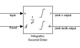
Resetting the State

The block can reset its states to the specified initial conditions based on an external signal. To cause the block to reset its states, select one of the External reset choices on the Attributes pane. A trigger port appears on the block below its input port and indicates the trigger type.

  • Select rising to reset the states when the reset signal rises from zero to a positive value, from a negative to a positive value, or a negative value to zero.

  • Select falling to reset the states when the reset signal falls from a positive value to zero, from a positive to a negative value, or from zero to negative.

  • Select either to reset the states when the reset signal changes from zero to a nonzero value or changes sign.

The reset port has direct feedthrough. If the block output feeds back into this port, either directly or through a series of blocks with direct feedthrough, an algebraic loop results (see Algebraic Loop Concepts).

Enabling Zero-Crossing Detection

This parameter controls whether zero-crossing detection is enabled for this block. By default, the Enable zero-crossing detection parameter is selected on the Attributes pane. However, this parameter is only in affect if the Zero-crossing control, on the Solver pane of the Configuration Parameters dialog box, is set to Use local settings. For more information, see Zero-Crossing Detection.

Reinitializing dx/dt When x Reaches Saturation

For certain modeling applications, dx/dt must be reinitialized when state x reaches its limits in order to pull x out of saturation immediately. You can achieve this by selecting Reinitialize dx/dt when x reaches saturation on the Attributes pane.

If this option is on, then at the instant when x reaches saturation, Simulink checks whether the current value of the dx/dt initial condition (parameter or signal) allows the state x to leave saturation immediately. If so, Simulink reinitializes state dx/dt with the value of the initial condition (parameter or signal) at that instant. If not, Simulink ignores this parameter at the current instant and sets dx/dt to zero to make the block states consistent.

This parameter only applies at the time when x actually reaches saturation limit. It does not apply at any future time when x is being held at saturation.

Refer to the sections on limiting the states for more information. For an example, see Simulation of Bouncing Ball.

Disregarding State Limits and External Reset for Linearization

For cases where you simplify your model by linearizing it, you can have Simulink disregard the limits of the states and the external reset by selecting Ignore state limits and the reset for linearization.

Specifying the Absolute Tolerance for the Block Outputs

By default Simulink software uses the absolute tolerance value specified in the Configuration Parameters dialog box (see Error Tolerances for Variable-Step Solvers) to compute the output of the integrator blocks. If this value does not provide sufficient error control, specify a more appropriate value for state x in the Absolute tolerance x field and for state dx/dt in the Absolute tolerance dx/dt field of the parameter dialog box. Simulink uses the values that you specify to compute the state values of the block.

Specifying the Display of the Output Ports

You can control whether to display the x or the dx/dt output port using the ShowOutput parameter. You can display one output port or both; however, you must select at least one.

Specifying the State Names

You can specify the name of x states and dx/dt states using the StateNameX and StateNameDXDT parameters. However, you must specify names for both or neither; you cannot specify names for just x or just dx/dt. Both state names must have identical type and length. Furthermore, the number of names must evenly divide the number of states.

Selecting All Options

When you select all options, the block icon looks like this.

Ports

Input

expand all

Input signal u to the integrator system, specified as a scalar, vector, or matrix.

This port does not have direct feedthrough.

Data Types: double

External signal specifying the initial condition x0 to the integrator system. You can specify the initial condition as a scalar, vector, or matrix.

This port has direct feedthrough.

Dependencies

To enable this input port, set the Initial condition source x parameter to external.

Data Types: double

External signal specifying the initial condition dx0 to the integrator system. You can specify the initial condition dx0 as a scalar, vector, or matrix.

This port has direct feedthrough.

Dependencies

To enable this input port, set the Initial condition source dx/dt parameter to external.

Data Types: double

The external reset signal is a scalar, vector, or matrix that resets the block states to the initial conditions.

This port has direct feedthrough.

Dependencies

To enable this input port, set the External reset parameter to rising, falling, or either.

Data Types: double

Output

expand all

x state output signal, provided as a scalar, vector, or matrix.

Data Types: double

dx state output signal, specified as a scalar, vector, or matrix.

Data Types: double

Parameters

expand all

x

Specify the source of the initial conditions for state x.

  • internal — Get the initial conditions of state x from the Initial condition x parameter.

  • external — Get the initial conditions of state x from an external block connected to the X0 input port.

Limitations

Simulink software does not allow the initial condition of this block to be inf or NaN.

Dependencies

Selecting internal enables the Initial condition x parameter and removes the X0 input port.

Selecting external disables the Initial condition x parameter and enables the X0 input port.

Programmatic Use

Block Parameter: ICSourceX
Type: character vector, string
Values: 'internal' | 'external'
Default: 'internal'

Specify the initial condition of state x.

Limitations

Simulink software does not allow the initial condition of this block to be inf or NaN.

Dependencies

To enable this parameter, set Initial condition source x to internal.

Setting Initial condition source x to external disables this parameter and enables the X0 input port.

Programmatic Use

Block Parameter: ICX
Type: character vector, string
Values: scalar | vector | matrix
Default: '0.0'

Limit state x of the block to a value between the Lower limit x and Upper limit x parameters. The default value of the Second-Order Integrator block is off. The default value of the Second-Order Integrator Limited is on.

  • To limit state x to a value between the Lower limit x and Upper limit x parameters, select this check box.

  • To remove range limitations on state x, clear this check box.

Dependencies

Selecting this check box enables the Upper limit x and Lower limit x parameters.

Programmatic Use

Block Parameter: LimitX
Type: character vector, string
Values: 'off' | 'on'
Default: 'off' (Second-Order Integrator) | 'on' (Second-Order Integrator Limited)

Specify the upper limit of state x. The default value for the Second-Order Integrator block is inf. The default value for the Second-Order Integrator Limited block is 1.

Tips

The upper saturation limit for state x must be strictly greater than the lower saturation limit.

Dependencies

To enable this parameter, select the Limit x check box.

Programmatic Use

Block Parameter: UpperLimitX
Type: character vector, string
Values: '1' | 'inf' | scalar | vector | matrix
Default: '1' (Second-Order Integrator Limited) | 'inf' (Second-Order Integrator)

Specify the lower limit of state x. The default value for the Second-Order Integrator block is -inf. The default value for the Second-Order Integrator Limited block is 0.

Tip

The lower saturation limit for state x must be strictly less than the upper saturation limit.

Dependencies

To enable this parameter, select the Limit x check box.

Programmatic Use

Block Parameter: LowerLimitX
Type: character vector, string
Values: '0' | '-inf' | scalar | vector | matrix
Default: '0' (Second-Order Integrator Limited) | '-inf' (Second-Order Integrator)

Enable wrapping of x between the Wrapped upper value x and Wrapped lower value x parameters. Enabling wrapping of x eliminates the need for zero-crossing detection, reduces solver resets, improves solver performance and accuracy, and increases simulation time span when modeling rotary and cyclic state trajectories.

If you specify Wrapped upper value x as inf and Wrapped lower value x as -inf, wrapping will never occur.

Dependencies

Selecting this check box enables Wrapped upper value x and Wrapped lower value x.

Programmatic Use

Block Parameter: WrapX
Type: character vector, string
Values: 'off' | 'on'
Default: 'off'

Specify the upper value for wrapping x.

Dependencies

To enable this parameter, select the Wrap x check box.

Programmatic Use

Block Parameter: WrappedUpperValueX
Type: character vector, string
Values: scalar | vector | matrix
Default: 'pi'

Specify the lower value for wrapping x.

Dependencies

To enable this parameter, select the Wrap x check box.

Programmatic Use

Block Parameter: WrappedLowerValueX
Type: character vector, string
Values: scalar | vector | matrix
Default: '-pi'

Specify the absolute tolerance for computing state x.

  • You can enter auto, –1, a positive real scalar or vector.

  • If you enter auto or –1, Simulink uses the absolute tolerance value in the Configuration Parameters dialog box (see Solver Pane) to compute state x.

  • If you enter a real scalar value, that value overrides the absolute tolerance in the Configuration Parameters dialog box and is used for computing all x states.

  • If you enter a real vector, the dimension of that vector must match the dimension of state x. These values override the absolute tolerance in the Configuration Parameters dialog box.

Programmatic Use

Block Parameter: AbsoluteToleranceX
Type: character vector, string
Values: 'auto' | '-1' | any positive real scalar or vector
Default: 'auto'

Assign a unique name to state x.

Tips

  • To assign a name to a single state, enter the name between quotes, for example, position'.

  • To assign names to multiple x states, enter a comma-delimited list surrounded by braces, for example, {'a', 'b', 'c'}. Each name must be unique.

  • The state names apply only to the selected block.

  • If you specify a state name for x, you must also specify a state name for dx/dt.

  • State names for x and dx/dt must have identical types and lengths.

  • The number of states must be evenly divided by the number of state names. You can specify fewer names than x states, but you cannot specify more names than x states. For example, you can specify two names in a system with four states. The first name applies to the first two states and the second name to the last two states. However, you must be consistent and apply the same scheme to the state names for dx/dt.

  • To assign state names with a variable in the MATLAB® workspace, enter the variable without quotes. A variable can be a character vector, string or a cell array.

Programmatic Use

Block Parameter: StateNameX
Type: character vector, string
Values: ' ' | user-defined
Default: ' '

dx/dt

Specify the source of initial conditions for state dx/dt as internal or external.

Limitations

Simulink software does not allow the initial condition of this block to be inf or NaN.

Dependencies

  • Selecting internal enables the Initial condition dx/dt parameter and removes the dx0 input port.

  • Selecting external disables the Initial condition dx/dt parameter and enables the dx0 input port.

Programmatic Use

Block Parameter: ICSourceDXDT
Type: character vector
Values: 'internal' | 'external'
Default: 'internal'

Specify the initial condition of state dx/dt.

Limitations

Simulink software does not allow the initial condition of this block to be inf or NaN.

Dependencies

  • Setting Initial condition source dx/dt to internal enables this parameter.

  • Setting Initial condition source dx/dt to external disables this parameter.

Programmatic Use

Block Parameter: ICDXDT
Type: character vector
Values: scalar | vector | matrix
Default: '0.0'

Limit the dx/dt state of the block to a value between the Lower limit dx/dt and Upper limit dx/dt parameters. The default value of the Second-Order Integrator block is off. The default value of the Second-Order Integrator Limited is on.

Tip

If you set saturation limits for x, then the interval defined by the Upper limit dx/dt and Lower limit dx/dt must contain zero.

Dependencies

Selecting this check box enables the Upper limit dx/dt and Lower limit dx/dt parameters.

Programmatic Use

Parameter: LimitDXDT
Type: character vector
Values: 'off' | 'on'
Default: 'off' (Second-Order Integrator) | 'on' (Second-Order Integrator Limited)

Specify the upper limit for state dx/dt.

Dependencies

If you limit x, then this parameter must have a strictly positive value.

To enable this parameter, select the Limit dx/dt check box.

Programmatic Use

Block Parameter: UpperLimitDXDT
Type: character vector
Values: scalar | vector | matrix
Default: 'inf'

Specify the lower limit for state dx/dt.

Dependencies

If you limit x, then this parameter must have a strictly negative value.

To enable this parameter, select the Limit dx/dt check box.

Programmatic Use

Block Parameter: LowerLimitDXDT
Type: character vector
Values: scalar | vector | matrix
Default: '-inf'

Specify the absolute tolerance for computing state dx/dt.

  • You can enter auto, –1, a positive real scalar or vector.

  • If you enter auto or –1, then Simulink uses the absolute tolerance value in the Configuration Parameters dialog box (see Solver Pane) to compute the dx/dt output of the block.

  • If you enter a numeric value, that value overrides the absolute tolerance in the Configuration Parameters dialog box.

Programmatic Use

Block Parameter: AbsoluteToleranceDXDT
Type: character vector, string, scalar, or vector
Values: 'auto' | '-1' | any positive real scalar or vector
Default: 'auto'

Assign a unique name to state dx/dt.

Tips

  • To assign a name to a single state, enter the name between quotes, for example, 'velocity'.

  • To assign names to multiple dx/dt states, enter a comma-delimited list surrounded by braces, for example, {'a', 'b', 'c'}. Each name must be unique.

  • The state names apply only to the selected block.

  • If you specify a state name for dx/dt, you must also specify a state name for x.

  • State names for x and dx/dt must have identical types and lengths.

  • The number of states must be evenly divided by the number of state names. You can specify fewer names than dx/dt states, but you cannot specify more names than dx/dt states. For example, you can specify two names in a system with four states. The first name applies to the first two states and the second name to the last two states. However, you must be consistent and apply the same scheme to the state names for x.

  • To assign state names with a variable in the MATLAB workspace, enter the variable without quotes. A variable can be a character vector, string, or a cell array.

Programmatic Use

Block Parameter: StateNameDXDT
Type: character vector, string
Values: ' ' | user-defined
Default: ' '

Attributes

Reset the states to their initial conditions when a trigger event occurs in the reset signal.

  • none — Do not reset the state to initial conditions.

  • rising — Reset the state when the reset signal rises from a zero to a positive value or from a negative to a positive value.

  • falling — Reset the state when the reset signal falls from a positive value to zero or from a positive to a negative value.

  • either — Reset the state when the reset signal changes from zero to a nonzero value or changes sign.

Programmatic Use

Block Parameter: ExternalReset
Type: character vector, string
Values: 'none' | 'rising' | 'falling' | 'either'
Default: 'none'

Select to enable zero-crossing detection. For more information, see Zero-Crossing Detection.

Programmatic Use

Parameter: ZeroCross
Type: character vector, string
Values: 'on' | 'off'
Default: 'on'

At the instant when state x reaches saturation, reset dx/dt to its current initial conditions.

Tip

The dx/dt initial condition must have a value that enables x to leave saturation immediately. Otherwise, Simulink ignores the initial conditions for dx/dt to preserve mathematical consistency of block states.

Programmatic Use

Block Parameter: ReinitDXDTwhenXreachesSaturation
Type: character vector, string
Values: 'off' | 'on'
Default: 'off'

For linearization purposes, have Simulink ignore the specified state limits and the external reset.

Programmatic Use

Block Parameter: IgnoreStateLimitsAndResetForLinearization
Type: character vector, string
Values: 'off' | 'on'
Default: 'off'

Specify the output ports on the block.

  • both — Show both x and dx/dt output ports.

  • x — Show only the x output port.

  • dx/dt — Show only the dx/dt output port.

Programmatic Use

Block Parameter: ShowOutput
Type: character vector, string
Values: 'both' | 'x' | 'dxdt'
Default: 'both'

Block Characteristics

Data Types

double

Direct Feedthrough

noa

Multidimensional Signals

no

Variable-Size Signals

no

Zero-Crossing Detection

yes

a Ports of this block have different direct feedthrough characteristics.

Extended Capabilities

Version History

Introduced in R2010a