Discrete-Time Integrator
Perform discrete-time integration or accumulation of signal
Libraries:
Simulink /
Commonly Used Blocks
Simulink /
Discrete
HDL Coder /
Discrete
HDL Coder /
HDL Floating Point Operations
Description
Use the Discrete-Time Integrator block in place of the Integrator block to create a purely discrete model. With the Discrete-Time Integrator block, you can:
Define initial conditions on the block dialog box or as input to the block
Define an input gain (K) value
Output the block state
Define upper and lower limits on the integral
Reset the state with an additional reset input
Output Equations
With the first time step, block state n = 0, with either initial output
y(0) = IC or initial state x(0) = IC,
depending on the Initial condition setting parameter
value.
For a given step n > 0 with simulation time
t(n), Simulink® updates output y(n) as follows:
Forward Euler method:
y(n) = y(n-1) + K*[t(n) - t(n-1)]*u(n-1)
Backward Euler method:
y(n) = y(n-1) + K*[t(n) - t(n-1)]*u(n)
Trapezoidal method:
y(n) = y(n-1) + K*[t(n)-t(n-1)]*[u(n)+u(n-1)]/2
Simulink automatically selects a state-space realization of these output
equations depending on the block sample time, which can be explicit or triggered.
When using explicit sample time, t(n)-t(n-1) reduces to the
sample time T for all n > 0.
Integration and Accumulation Methods
This block can integrate or accumulate a signal using a forward Euler, backward Euler, or
trapezoidal method. Assume that u is the input,
y is the output, and x is the state. For a
given step n, Simulink updates y(n) and x(n+1). In
integration mode, T is the block sample time (delta
T in the case of triggered sample time). In accumulation
mode, T = 1. The block sample time determines when the output is
computed but not the output value. K is the gain value. Values
clip according to upper or lower limits.
Forward Euler method (default), also known as forward rectangular, or left-hand approximation
The software approximates 1/s as
T/(z-1). The expressions for the output of the block at step
n are:
x(n+1) = x(n) + K*T*u(n)
y(n)   = x(n)
The block uses these steps to compute the output:
Step 0:          y(0)   = IC (clip if necessary)
                 x(1)   = y(0) + K*T*u(0)

Step 1:          y(1)   = x(1)
                 x(2)   = x(1) + K*T*u(1)

Step n:          y(n)   = x(n)
                 x(n+1) = x(n) + K*T*u(n) (clip if necessary)
Using this method, input port 1 does not have direct feedthrough.
Backward Euler method, also known as backward rectangular or right-hand approximation
The software approximates 1/s as
T*z/(z-1). The resulting expression for the output of the
block at step n is
y(n) = y(n-1) + K*T*u(n).
Let x(n) = y((n)-1). The block uses these steps to compute
the output.
If the parameter Initial condition setting is set to
OutputorAutofor triggered and function-call subsystems:Step 0: y(0) = IC (clipped if necessary) x(1) = y(0)If the parameter Initial condition setting is set to
Autofor non-triggered subsystems:Step 0: x(0) = IC (clipped if necessary) x(1) = y(0) = x(0) + K*T*u(0) Step 1: y(1) = x(1) + K*T*u(1) x(2) = y(1) Step n: y(n) = x(n) + K*T*u(n) x(n+1) = y(n)
Using this method, input port 1 has direct feedthrough.
For this method, the software approximates 1/s as
T/2*(z+1)/(z-1).
When T is fixed (equal to the sampling period), the
expressions to compute the output are:
x(n) = y(n-1) + K*T/2*u(n-1)
y(n) = x(n) + K*T/2*u(n)
If the parameter Initial condition setting is set to
OutputorAutofor triggered and function-call subsystems:Step 0: y(0) = IC (clipped if necessary) x(1) = y(0) + K*T/2*u(0)If the parameter Initial condition setting is set to
Autofor non-triggered subsystems:Step 0: x(0) = IC (clipped if necessary) y(0) = x(0) + K*T/2*u(0) x(1) = y(0) + K*T/2*u(0) Step 1: y(1) = x(1) + K*T/2*u(1) x(2) = y(1) + K*T/2*u(1) Step n: y(n) = x(n) + K*T/2*u(n) x(n+1) = y(n) + K*T/2*u(n)
Here, x(n+1) is the best estimate of the next output. It is
not the same as the state, in that x(n) is not equal to
y(n).
Using this method, input port 1 has direct feedthrough.
WhenT is a variable (for example, obtained from the
triggering times), the block uses these steps to compute the output.
If the parameter Initial condition setting is set to
OutputorAutofor triggered and function-call subsystems:Step 0: y(0) = IC (clipped if necessary) x(1) = y(0)If the parameter Initial condition setting is set to
Autofor non-triggered subsystems:Step 0: x(0) = IC (clipped if necessary) x(1) = y(0) = x(0) + K*T/2*u(0) Step 1: y(1) = x(1) + K*T/2*(u(1) + u(0)) x(2) = y(1) Step n: y(n) = x(n) + K*T/2*(u(n) + u(n-1)) x(n+1) = y(n)
Define Initial Conditions
You can define the initial conditions as a parameter on the block dialog box or input them from an external signal:
To define the initial conditions as a block parameter, set the Initial condition source parameter to
internaland enter the value in the Initial condition text box.To provide the initial conditions from an external source, set the Initial condition source parameter to
external. An additional input port appears on the block.
When to Use the State Port
Use the state port instead of the output port:
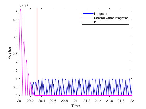
When the output of the block is fed back into the block through the reset port or the initial condition port, causing an algebraic loop. For an example, see the
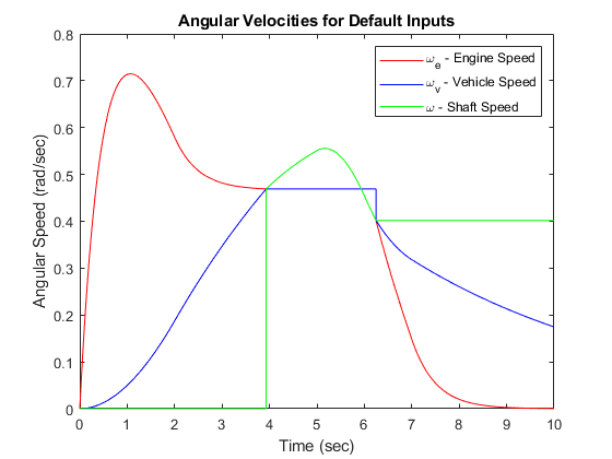
sldemo_bounce_two_integratorsmodel.When you want to pass the state from one conditionally executed subsystem to another, which can cause timing problems. For an example, see Building a Clutch Lock-Up Model.
You can work around these problems by passing the state through the state port rather than the output port. Simulink generates the state at a slightly different time from the output, which protects your model from these problems. To output the block state, select the Show state port check box. The state port appears on the top of the block.

Limit the Integral
To keep the output within certain levels, select the Limit output check box and enter the limits in the corresponding text box. Doing so causes the block to function as a limited integrator. When the output reaches the limits, the integral action turns off to prevent integral windup. During a simulation, you can change the limits but you cannot change whether the output is limited. The table shows how the block determines output.
| Integral | Output |
|---|---|
| Less than the Lower saturation limit | Held at the Lower saturation limit |
| Between the Lower saturation limit and the Upper saturation limit | The integral |
| Greater than the Upper saturation limit | Held at the Upper saturation limit |
To generate a signal that indicates when the integral reaches limit, select the Show saturation port check box. A new saturation port appears below the block output port.

The saturation signal has one of three values:
1 indicates that the integral is at the upper limit.
0 indicates that the integral is not limited.
-1 indicates that the integral is at the lower limit.
Reset the State
The block resets its state to the specified initial condition, based on an external signal. To cause the block to reset its state, select one of the External reset parameter options. A reset port appears that indicates the reset trigger type.

The reset port has direct feedthrough. If the block output feeds back into this port, either directly or through a series of blocks with direct feedthrough, an algebraic loop results. To resolve this loop, feed the output of the block state port into the reset port instead. To access the block state, select the Show state port check box.
Reset Trigger Types
The External reset parameter lets you determine the attribute of the reset signal that triggers the reset. The trigger options include:
rising– Resets the state when the reset signal has a rising edge. For example, this figure shows the effect that a rising reset trigger has on backward Euler integration.
falling— Resets the state when the reset signal has a falling edge. For example, this figure shows the effect that a falling reset trigger has on backward Euler integration.
either— Resets the state when the reset signal rises or falls. For example, the following figure shows the effect that an either reset trigger has on backward Euler integration.
level— Resets and holds the output to the initial condition while the reset signal is nonzero. For example, this figure shows the effect that a level reset trigger has on backward Euler integration.
sampled level— Resets the output to the initial condition when the reset signal is nonzero. For example, this figure shows the effect that a sampled level reset trigger has on backward Euler integration.
The
sampled levelreset option requires fewer computations, making it more efficient than thelevelreset option.Note
For the Discrete-Time Integrator block, all trigger detections are based on signals with positive values. For example, a signal changing from -1 to 0 is not considered a rising edge, but a signal changing from 0 to 1 is.
Behavior in Simplified Initialization Mode
Simplified initialization mode is enabled when you set Underspecified
initialization detection to Simplified in
the Configuration Parameters dialog box. If you use simplified initialization mode,
the behavior of the Discrete-Time Integrator block differs from
classic initialization mode. The new initialization behavior is more robust and
provides more consistent behavior in these cases:
In algebraic loops
On enable and disable
When comparing results using triggered sample time against explicit sample time, where the block is triggered at the same rate as the explicit sample time
Simplified initialization mode enables easier conversion from Continuous-Time Integrator blocks to Discrete-Time Integrator blocks, because the initial conditions have the same meaning for both blocks.
For more information on classic and simplified initialization modes, see Underspecified initialization detection.
When you use simplified initialization mode with Initial condition
setting set to Output for triggered
and function-call subsystems, the enable and disable behavior of the block is
simplified as follows.
At disable time td:
y(td) = y(td-1)
At enable time te:
If the parent subsystem control port has States when enabling set to
reset:y(te) = IC.
If the parent subsystem control port has States when enabling set to
held:y(te) = y(td).
The following figure shows this condition.

When using simplified initialization mode, you cannot place the Discrete-Time Integrator block in an iterator subsystem block.
In simplified initialization mode, Iterator subsystems do not maintain elapsed time. Thus, if a Discrete-Time Integrator block, which needs elapsed time, is placed inside an iterator subsystem block, Simulink reports an error.
Behavior in an Enabled Subsystem Inside a Function-Call Subsystem
Suppose you have a function-call subsystem that includes an enabled subsystem, which contains a Discrete-Time Integrator block. The following behavior applies.
| Integrator Method | Sample Time Type of Function-Call Trigger Port | Value of delta T When
Function-Call Subsystem Executes for the First Time After Enabled | Reason for Behavior |
|---|---|---|---|
Forward Euler | Triggered |
| When the function-call subsystem executes for the first
time, the integrator algorithm uses |
Backward Euler and Trapezoidal | Triggered |
| When the function-call subsystem executes for the first
time, the integrator algorithm uses |
Forward Euler, Backward Euler, and Trapezoidal | Periodic | Sample time of the function-call generator | In periodic mode, the Discrete-Time
Integrator block uses sample time of the
function-call generator for |
Examples

Ports
Input
Output
Parameters
Block Characteristics
Data Types |
|
Direct Feedthrough |
|
Multidimensional Signals |
|
Variable-Size Signals |
|
Zero-Crossing Detection |
|
Extended Capabilities
Version History
Introduced before R2006a
See Also
Topics
- C Data Code Interface Configuration for Model Interface Elements (Simulink Coder)
- C Data Code Interface Configuration for Model Interface Elements (Simulink Coder)
- Organize Parameter Data into a Structure by Using Struct Storage Class (Embedded Coder)
You can also select a web site from the following list:
Americas
- América Latina (Español)
- Canada (English)
- United States (English)
Europe
- Belgium (English)
- Denmark (English)
- Deutschland (Deutsch)
- España (Español)
- Finland (English)
- France (Français)
- Ireland (English)
- Italia (Italiano)
- Luxembourg (English)
- Netherlands (English)
- Norway (English)
- Österreich (Deutsch)
- Portugal (English)
- Sweden (English)
- Switzerland
- United Kingdom (English)