Simulation Phases in Dynamic Systems
Model Compilation
The first phase of simulation occurs when the system’s model is open and you simulate the model. In the Simulink® Editor, click Run. Running the simulation causes the Simulink engine to invoke the model compiler. The model compiler converts the model to an executable form, a process called compilation. In particular, the compiler:
Evaluates the model's block parameter expressions to determine their values.
Determines signal attributes, e.g., name, data type, numeric type, and dimensionality, not explicitly specified by the model and checks that each block can accept the signals connected to its inputs.
Propagates the attributes of a source signal to the inputs of the blocks that it drives in order to compute previously unspecified attributes in the blocks.
Performs block reduction optimizations.
Flattens the model hierarchy by replacing virtual subsystems with the blocks that they contain (see Compare Solvers).
Determines the block execution order by task-based sorting.
Determines the sample times of all blocks in the model whose sample times you did not explicitly specify (see How Propagation Affects Inherited Sample Times).
These events are essentially the same as what occurs when you update a diagram. The difference is that the Simulink software starts model compilation as part of model simulation, where compilation leads directly into the linking phase, as described in Link Phase. In contrast, you start an explicit model update as a standalone operation on a model.
When you compile a model or model hierarchy, you can cancel model compilation by clicking the Cancel button next to the progress bar.
Link Phase
In this phase, the Simulink engine allocates memory needed for working areas (signals, states, and run-time parameters) for execution of the block diagram. It also allocates and initializes memory for data structures that store run-time information for each block. For built-in blocks, the principal run-time data structure for a block is called the SimBlock. It stores pointers to a block's input and output buffers and state and work vectors.
Method Execution Lists
In the Link phase, the Simulink engine also creates method execution lists. These lists list the most efficient order in which to invoke a model's block methods to compute its outputs. The block execution order lists generated during the model compilation phase are used to construct the method execution lists.
Block Priorities
You can assign update priorities to blocks. The output methods of higher priority blocks are executed before those of lower priority blocks. These priorities are honored only if they are consistent with its block execution order.
Simulation Loop Phase
Once the Link Phase completes, the simulation enters the simulation loop phase. In this phase, the Simulink engine successively computes the states and outputs of the system at intervals from the simulation start time to the finish time, using information provided by the model. The successive time points at which the states and outputs are computed are called time steps. The length of time between steps is called the step size. The step size depends on the type of solver (see Compare Solvers) used to compute the system's continuous states, the system's fundamental sample time (see Sample Times in Systems and Subsystems), and whether the system's continuous states have discontinuities (see Zero-Crossing Detection).
The Simulation Loop phase has two subphases: the Loop Initialization phase and the Loop Iteration phase. The initialization phase occurs once, at the start of the loop. The iteration phase is repeated once per time step from the simulation start time to the simulation stop time.
At the start of the simulation, the model specifies the initial states and outputs of the system to be simulated. At each step, new values for the system's inputs, states, and outputs are computed, and the model is updated to reflect the computed values. At the end of the simulation, the model reflects the final values of the system's inputs, states, and outputs. The Simulink software provides data display and logging blocks. You can display and/or log intermediate results by including these blocks in your model.
The following flowchart explains how the simulation loop works where
k denotes the major step counter: 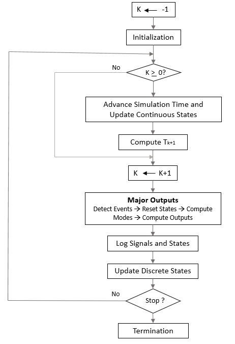
Loop Iteration
At each time step, the Simulink engine:
Computes the model outputs.
The Simulink engine initiates this step by invoking the Simulink model Outputs method. The model Outputs method in turn invokes the model system Outputs method, which invokes the Outputs methods of the blocks that the model contains in the order specified by the Outputs method execution lists generated in the Link phase of the simulation (see Compare Solvers).
The system Outputs method passes the following arguments to each block Outputs method: a pointer to the block's data structure and to its SimBlock structure. The SimBlock data structures point to information that the Outputs method needs to compute the block's outputs, including the location of its input buffers and its output buffers.
Computes the model's states.
The Simulink engine computes a model's states by invoking a solver. Which solver it invokes depends on whether the model has no states, only discrete states, only continuous states, or both continuous and discrete states.
If the model has only discrete states, the Simulink engine invokes the discrete solver selected by the user. The solver computes the size of the time step needed to hit the model's sample times. It then invokes the Update method of the model. The model Update method invokes the Update method of its system, which invokes the Update methods of each of the blocks that the system contains in the order specified by the Update method lists generated in the Link phase.
If the model has only continuous states, the Simulink engine invokes the continuous solver specified by the model. Depending on the solver, the solver either in turn calls the Derivatives method of the model once or enters a subcycle of minor time steps where the solver repeatedly calls the model's Outputs methods and Derivatives methods to compute the model's outputs and derivatives at successive intervals within the major time step. This is done to increase the accuracy of the state computation. The model Outputs method and Derivatives methods in turn invoke their corresponding system methods, which invoke the block Outputs and Derivatives in the order specified by the Outputs and Derivatives methods execution lists generated in the Link phase.
Optionally checks for discontinuities in the continuous states of blocks.
A technique called zero-crossing detection is used to detect discontinuities in continuous states. See Zero-Crossing Detection for more information.
Computes the time for the next time step.
Steps 1 through 4 are repeated until the simulation stop time is reached.
Related Topics
You can also select a web site from the following list:
Americas
- América Latina (Español)
- Canada (English)
- United States (English)
Europe
- Belgium (English)
- Denmark (English)
- Deutschland (Deutsch)
- España (Español)
- Finland (English)
- France (Français)
- Ireland (English)
- Italia (Italiano)
- Luxembourg (English)
- Netherlands (English)
- Norway (English)
- Österreich (Deutsch)
- Portugal (English)
- Sweden (English)
- Switzerland
- United Kingdom (English)